Robot Arm
Restoration and software integration of a 6-axis robot arm.
Introduction
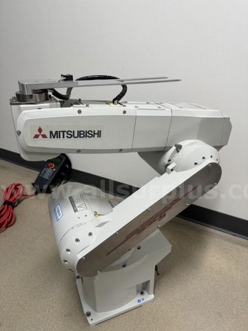
In 2025, I acquired a used 6-axis Mitsubishi RV-6SDL-S15 industrial robot arm from a Procter & Gamble facility in Ohio through an industrial equipment auction for $500. Previously deployed in a high-volume manufacturing line, this industrial-grade robot represents a unique opportunity to build hands-on expertise in robotics control systems, automation integration, and R&D prototyping.
This project bridges production automation experience with advanced robotics research—combining mechanical restoration, controls engineering, and software integration to create a versatile platform for exploring automation concepts directly applicable to advanced manufacturing and R&D environments.
Technical Specifications
| Specification | Details |
|---|---|
| Model | Mitsubishi RV-6SDL-S15 |
| Axes | 6 (J1-J6 fully articulated) |
| Reach | ~900mm (35.4”) working radius |
| Payload | 6kg (13.2 lbs) rated capacity |
| Repeatability | ±0.02mm (industrial precision) |
| Controller | Mitsubishi CR2DA-700 |
| Communication | Ethernet (Modbus/TCP), RS-232 Serial |
| Drive System | AC Servo motors with harmonic drives |
| Power | 200-240V AC, 3-phase |
| Application | Originally: P&G manufacturing line |
| Acquisition | 2025, Industrial auction ($500) |
Project Status
Current Phase: Software integration and control system development Timeline: 6+ months of active restoration and development Status: Mechanically operational, actively developing high-level control interface Next Milestone: ROS MoveIt! integration for motion planning
Setting Up
The first step was to create a dedicated workspace and gather all necessary tools. I cleared a large workbench, ensuring adequate lighting and power access, and assembled essential equipment including a digital multimeter, oscilloscope, various sizes of hex keys, torque wrenches, and specialized lubricants. I carefully unboxed the arm, photographing each step of the process and creating detailed documentation of its initial state. The robot showed signs of extended storage—there was light surface corrosion on some exposed metal parts, and the cables had become stiff from age.
I methodically inspected and documented every visible component. The arm’s six joints were manually articulated to assess their range of motion and identify any concerning sounds or resistance. I tested each servo motor’s electrical connections, checking for continuity and proper insulation. The controller box was opened and examined for any obvious damage or loose connections. Throughout this process, I maintained a detailed log of observations, creating a comprehensive checklist of items that needed attention. My goal was to systematically inspect every component—from mechanical parts to electrical connections—and determine the root cause of its malfunction before attempting any repairs.
Troubleshooting and Disassembly
Early diagnostics pointed to issues with the J2 axis, specifically irregular motion and concerning vibrations during operation. I began by disassembling this section of the robot, which led me to focus on the harmonic drive and the AC servo motor. The harmonic drive showed signs of wear and contamination—the wave generator exhibited minor scoring marks, while the flex spline contained accumulated debris that impeded smooth operation. I carefully took apart the J2 axis, cleaning the harmonic drive thoroughly using specialized solvents to remove debris and hardened grease, followed by applying fresh SHF-32 lubricant to ensure proper operation. The circular spline teeth required particular attention, as they showed signs of uneven wear that needed careful cleaning and inspection.
Similarly, I disassembled and cleaned the AC servo motor, discovering that the bearings had accumulated significant debris and the encoder disk showed signs of contamination. I methodically addressed each component—cleaning the stator windings, replacing the bearings, and carefully realigning the encoder disk to ensure accurate position feedback. The process of reassembly required precise torque specifications for the mounting bolts and careful alignment of the motor shaft with the harmonic drive input.
This restoration process involved a fair amount of trial and error, particularly in achieving the correct preload on the harmonic drive and proper encoder alignment. I developed a systematic testing procedure, gradually increasing the range of motion while monitoring current draw and vibration levels. Through iterative adjustments and careful calibration of each component, I was able to restore the axis to smooth, reliable operation with minimal backlash and proper position accuracy.
Communication with the Controller
After resolving the mechanical issues, I turned my attention to the robot’s control systems. The controller uses a proprietary communication protocol, requiring careful reverse engineering to establish reliable connectivity. I began by analyzing the electrical signals using an oscilloscope to understand the timing and voltage levels of the communication interface.
Leveraging Industrial Controls Experience: My professional background with Siemens PCS7 DCS systems proved invaluable in this phase. Experience with industrial communication protocols (Profibus, Profinet), SCADA architectures, and safety-rated control systems directly informed my approach to interfacing with the Mitsubishi controller. The concepts of deterministic communication, real-time control loops, and safety interlocking from DCS engineering translate directly to robotic control systems.
My current efforts are focused on establishing reliable communication with the controller through multiple approaches:
- TCP/IP Communication: Implemented a custom socket server listening on port 502 (Modbus/TCP), and a Python client for sending movement commands and receiving position feedback.
- Serial Communication: Experimented with RS‑232 at 115200 baud, 8N1, tuning baud rates and framing to achieve stable data exchange.
- RT Toolbox2 Integration:
- Configured Mitsubishi’s RT Toolbox2 software to communicate over TCP/IP with the CR2DA‑700 controller at IP 192.168.0.20.
- Developed MELFA BASIC scripts and uploaded them via RT Toolbox2’s project manager. These scripts include custom movement routines, homing sequences, and I/O diagnostics.
- Automated the deployment process: on startup, the host PC launches an RT Toolbox2 API session, loads the latest MELFA BASIC program, and triggers a self‑test routine on each axis.
- Utilized RT Toolbox2’s online monitor to log real‑time joint angles, motor currents, and error codes—feeding this telemetry back into my Python dashboard for visualization and alerting.
- Error Handling: Added CRC checksums, timeout/retry mechanisms, and a state machine to manage the connection lifecycle.
While the integration poses challenges—such as configuring network settings, handling packet loss, and ensuring consistent data transmission—I’ve made substantial progress toward a high‑level API that abstracts these complexities.
Achievements & Technical Specs
Robot arm demonstration: movements, calibration, and control interface
System Architecture
┌─────────────────────────────────────────────────────────────────┐
│                    🔧 HARDWARE LAYER                            │
├─────────────────────────────────────────────────────────────────┤
│  Mitsubishi RV-6SDL-S15        ←→    CR2DA-700 Controller      │
│  (6-Axis Robot Arm)                  (Servo Drives & Logic)    │
│  • 6kg payload, 900mm reach          • Real-time motion control│
│  • Harmonic drives, AC servos        • Safety interlocks       │
└──────────────────┬──────────────────────────┬───────────────────┘
                   │                          │
        ┌──────────▼──────────┐    ┌─────────▼──────────┐
        │  Ethernet (TCP/IP)  │    │   RS-232 Serial    │
        │  192.168.0.20:502   │    │   115200 baud      │
        │  Modbus/TCP         │    │   8N1              │
        └──────────┬──────────┘    └─────────┬──────────┘
┌──────────────────┴───────────────────────┴────────────────────┐
│              🔌 COMMUNICATION LAYER                            │
│  • CRC checksums  • Timeout/retry  • State machine mgmt       │
└──────────────────┬────────────────────────────────────────────┘
                   │
        ┌──────────▼──────────────────────────┐
        │    💻 SOFTWARE INTEGRATION          │
        ├─────────────────────────────────────┤
        │  RT Toolbox2    Python Interface    │
        │  • MELFA BASIC  • Socket client     │
        │  • Monitoring   • Serial comm       │
        │  • Diagnostics  • Error handling    │
        │                                     │
        │  ROS Integration (Future)           │
        │  • URDF model  • MoveIt! planning   │
        └──────────────────┬──────────────────┘
                           │
        ┌──────────────────▼──────────────────┐
        │    👤 USER INTERFACE LAYER          │
        ├─────────────────────────────────────┤
        │  • Web Dashboard (telemetry)        │
        │  • Joystick Control (manual)        │
        │  • RESTful API (automation)         │
        └─────────────────────────────────────┘

🏭 Industrial Controls Context (Siemens PCS7 DCS):
   • Communication protocols (Profibus/Profinet concepts)
   • SCADA architecture patterns
   • Safety systems design (SIL-rated)
   • Real-time control loops
Key Architecture Features:
- Modular Design: Communication layer abstracts hardware details
- Dual Interface: Ethernet (primary) and Serial (diagnostic/backup)
- Robust Error Handling: CRC validation, timeouts, retry logic
- Scalable: Designed for future ROS/MoveIt! integration
- DCS-Informed: Safety and reliability principles from industrial automation
Key Achievements to Date:
- Mechanical Restoration: Complete refurbishment of all six axes, especially the J2 harmonic drive and AC servo motor.
- Software Integration: Functional TCP/IP & RS‑232 clients with robust error handling and calibration routines.
- Testing & Calibration: Iterative motion tests, current monitoring, and vibration analysis for reliable, backlash‑free operation.
Technical Specifications:
- 6‑Axis Articulation: Independently driven joints for full 3D workspace coverage.
- Harmonic Drive: High‑precision wave generator and flex spline in the J2 axis.
- Servo Motors: AC servos with custom bearing replacements and encoder realignment.
- Controller Interfaces: Dual-mode Ethernet (Modbus/TCP) and RS‑232 serial connectivity.
- Documentation: Detailed logs, calibration checklists, and step-by-step photographs.
Computer Vision Integration
Building on the communication and control foundation, I’ve begun integrating machine vision capabilities to enable vision-guided automation and adaptive control workflows.
Current Implementation:
- OpenCV Integration: Python-based vision processing pipeline for real-time object detection and tracking
- Camera Setup: USB webcam mounted to workspace for proof-of-concept vision-guided operations
- Coordinate Transformation: Developing camera-to-robot coordinate mapping for vision-based positioning
- Adaptive Control: Exploring closed-loop visual servoing for dynamic object interaction
Vision System Architecture:
Camera → OpenCV Processing → Object Detection → Coordinate Transform → Robot Commands
   ↓           ↓                    ↓                   ↓                    ↓
  USB      Python CV2         Blob/Edge/Color      Calibration Matrix   TCP/IP Interface
Applications Being Explored:
- Vision-Guided Pick-and-Place: Object localization and grasping using visual feedback
- Quality Inspection Workflows: Automated visual inspection of parts or assemblies
- Adaptive Task Execution: Real-time trajectory adjustment based on visual input
- Object Recognition: Identifying and classifying components for automated handling
This vision integration represents a natural evolution toward adaptive automation—combining robotic manipulation with real-time sensor feedback to handle variable environments and dynamic tasks, directly applicable to R&D automation and advanced manufacturing scenarios.
Next Steps:
- Intel RealSense depth camera integration for 3D object localization
- Machine learning-based object classification and pose estimation
- Integration with ROS MoveIt! for vision-informed motion planning
End-Effector & Tooling Development
To expand the robot’s capabilities beyond basic motion control, I’m developing custom end-effectors and tooling tailored to specific automation tasks—bridging mechanical design with robotic manipulation.
Current Development:
- Modular Tool Interface: Designing a quick-change tool plate for the J6 flange, enabling rapid switching between end-effectors
- Gripper Design: CAD modeling of a parallel-jaw gripper actuated by pneumatic or servo drive
- Design for Automation: Applying DFA principles to ensure repeatable, reliable tool mounting and operation
- 3D Printing & Iteration: Prototyping gripper components using additive manufacturing for rapid design validation
Design Approach:
Task Requirements → CAD Design → Prototype (3D Print) → Test & Iterate → Production Method
       ↓                ↓              ↓                    ↓                  ↓
  Payload/Reach    SolidWorks      FDM/SLA Printing    Performance Eval    CNC/Injection
Tooling Applications Being Explored:
- Parallel Gripper: For pick-and-place operations with prismatic objects
- Soft Gripper: Compliant gripping for delicate or irregular parts
- Custom Jigs/Fixtures: Task-specific tooling for assembly or inspection workflows
- Sensor Integration: Force/torque sensors and tactile feedback for adaptive grasping
This end-effector work demonstrates the mechanical-robotic integration essential for R&D automation—combining CAD design, rapid prototyping, and iterative testing to create task-specific automation solutions.
Relevance to Automation Engineering: End-effector design is a critical component of automation cell development. Understanding how to design, prototype, and optimize tooling for specific tasks—while integrating with robotic controllers and vision systems—is foundational for advanced manufacturing automation and R&D engineering roles.
Future Directions
- Custom Control Interface
- Web‑based dashboard and manual joystick control.
- High‑Level API
- RESTful endpoints for motion commands, sensor data, and status monitoring.
- Path Planning & Collision Detection
- Integration of motion planning libraries (e.g., MoveIt!) for safe, autonomous trajectories.
- Advanced Vision Capabilities
- Intel RealSense depth camera, ML-based pose estimation, and human-robot collaboration safety.
- Telemetry & Analytics
- Real‑time data logging of position, torque, and error states for predictive maintenance and performance tuning.
- Community Engagement
- Publishing tutorials, code samples, and collaborating with other robotics enthusiasts.
Code Repository
The Python control scripts and ROS integration code for this project are available on GitHub. The repository includes:
-
robot_control/: Python modules for TCP/IP and serial communication -
ros_workspace/: ROS packages for robot interface -
config/: Controller configuration files -
docs/: Technical documentation and calibration procedures
Conclusion
Restoring and integrating this robot arm has been an in‑depth exploration of mechanical engineering, electronics diagnostics, and software development. From harmonic drive calibration to protocol reverse engineering, every phase has deepened my expertise in industrial robotics.
Relevance to R&D Automation Engineering: This project demonstrates end-to-end capability in automation systems—from mechanical understanding to controls engineering to software integration. The iterative R&D methodology, documentation rigor, and cross-functional technical skills mirror the requirements of advanced manufacturing automation roles.